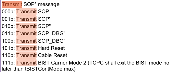
5 Sending a USB PD message The general steps of transmitting a SOP* message are listed below. Please consult sections 4.7.1, 4.7.2, and 4.7.3 of the TCPC specification[3] for more detailed implementation and examples. • Step 0: TCPM writes the content of the message to be transmitted into the TRANSMIT_BUFFER • Step 1: TCPM writes to TRANSMIT requesting SOP* transmission • Step 2: The outcome reported by the TCPC may be one of three indications after asserting the Alert# pin: – If the TCPC PHY layer successfully transmits the message, the TCPC sets the Transmission Successful bit in the ALERT register. – If the TCPC PHY layer did not get any response after retries, the TCPC sets the Transmission Failed bit in the ALERT register. – If the transmission was discarded due to an incoming message, the TCPC sets the Transmission Discarded bit in the ALERT register. • Step 3: Before requesting another transmission, the TCPM shall clear the alert by writing a 1 to the asserted bit in the ALERT register. When transitioning through the steps of transmitting SOP* message, TCPC may assert ALERT.ReceiveStatus or ALERT.ReceivedHardReset bit at any time to notify that a message was received.
4.7 USB PD Communication Operational Model 4.7.1 Transmitting an SOP* USB PD Message with Less than or Equal to 128 Data Bytes 4.7.2 Transmitting an SOP* USB PD Message with Greater than 128 Data Bytes 4.7.3 Transmitting a Hard Reset Message
Narrow-VDC (NVDC) Power Path Management – Instant-On With No Battery or Deeply Discharged Battery – Battery Supplements System When Adapter is Fully-Loaded
8.4.1.1 System Voltage Regulation with Narrow VDC Architecture The bq25703A employs Narrow VDC architecture (NVDC) with BATFET separating system from battery. The minimum system voltage is set by MinSystemVoltage(). Even with a deeply depleted battery, the system is regulated above the minimum system voltage. When the battery is below minimum system voltage setting, the BATFET operates in linear mode (LDO mode). As the battery voltage rises above the minimum system voltage, BATFET is fully on when charging or in supplement mode and the voltage difference between the system and battery is the VDS of BATFET. System voltage is regulated 160 mV above battery voltage when BATFET is off (no charging or no supplement current).
This figure shows the Narrow VDC (NVDC) topology. Here, the system bus (Vsys) is not connected directly to the adapter. It is connected to the output of the buck converter. Hence, NVDC operates only as a buck converter, both when NVDC charges the battery and when the battery supplements the adapter and provides power to the system. NVDC implementation reduces the switch-over period between the charging mode and the hybrid power mode. NVDC implementation allows the system to minimize the period of overloading the input power source when CPU is in Turbo Boost mode.
The advantage of using the NVDC system is that the overall system efficiency is better compared to the Hybrid Power Boost (HPB) charger. The system can be designed for a smaller voltage rating since the system has a lower Vin. The disadvantage is that the charger components’ size and power dissipation increases.
USB-C 되면서 양방향으로 작동하는게 추가된 듯 한데 그게 바로 DRP(Dual Role) 인 듯
그러니까.. DRP를 지원하면 충전할 수도 있고, 남을 위해 전기도 내어줄수 있...다?
DFP(Downstream Facing Port)는 호스트 또는 허브에 설치되고 장치에 연결되는 USB Type-C 포트입니다. UFP(Upstream Facing Port)는 호스트 또는 허브에 연결된 USB Type-C 포트, 장치 또는 허브의 DFP입니다. DRP(Dual Role Port, 이중 목적 전원 역할은 USB Type-C 포트에서 소스 또는 싱크 역할로 사용할 수 있는 정의입니다.
PTN5110 is a single-port TCPC compliant USB Power Delivery (PD) PHY IC that implements Type-C Configuration Channel (CC) interface and USB PD Physical layer functions to a Type-C Port Manager (TCPM)that handles PD Policy management