'회사일/전자부품'에 해당되는 글 6건

  1. 2025.01.15 ptn5110 usb-pd rdo 응답
  2. 2025.01.06 ad5292 wiper 값
  3. 2024.11.13 ads8598
  4. 2024.11.07 ad4111
  5. 2024.11.07 ad5292 write protect
  6. 2024.09.26 ad5291 shutdown mode
회사일/전자부품2025. 1. 15. 18:04

RDO로 요청하니 PDO를 아래와 같이 받았다고 하는데

61 2C 91 01 08 2C D1 02 00 2C C1 03 00 2C B1 04 00 45 41 06 00 64 21 DC C0


PDO 형태는 이렇게 생겨 먹었다고 하고


PDO 타입에 따라 상관없이 19-10 / 9-0은 거의 동일한데


그걸 정리하면 다음과 같이

최소 전압은 50mV 단위로, 전류는 10mA 단위로 계산하면 어찌 될 듯


받은대로 해석해보니 영 엉뚱한 값만 나와서


I2C를 통해 받은거라 혹시 데이터가 뒤쪽부터 반대로 받아진거 아니야? 하면서 바이트 순서를 뒤집고

바이트를 msb와 lsb에 맞춰서 정렬하고 10비트씩 잘라서 해석해보니

먼가 그럴싸하게 20v / 15v / 12v / 9v / 5v가 나오는 것 같기도 하고..

5V 3A는 dual role power로 마킹된걸려나?


일단 USB PD 충전기에서

C1 커넥터에 연결했고

5.0V 3.0A = 15W

9.0V 3.0A = 27W

12.0V 3.0A = 36W

15V 3.0A = 45W

20.0V 3.25A = 65W

PPS 3.3V~11V = 3A 라고 되어있다.

가장 처음 4바이트를 반대로 다시 파싱해보고

가장 마지막 61이 먼지도 봐야 할 듯.. bargage 였거나 trailing EOF 이거나.. 혹은 parity 이거나.. 어느걸려나?

'회사일 > 전자부품' 카테고리의 다른 글

ad5292 wiper 값  (0) 2025.01.06
ads8598  (0) 2024.11.13
ad4111  (0) 2024.11.07
ad5292 write protect  (0) 2024.11.07
ad5291 shutdown mode  (0) 2024.09.26
Posted by 구차니
회사일/전자부품2025. 1. 6. 17:21

아니~~~~!!!

값을 설정하면 당연히(?) A-W 의 저항으로 될 줄 알았는데


데이터 시트를 잘보니.. 어..? R_WB... 엥?


아니아니!!! 왜 도대체 R_WB 수식을 먼저 보여주고 R_WA를 나중에 보여주냐고 ㅠㅠ

[링크 : https://www.analog.com/media/en/technical-documentation/data-sheets/ad5291_5292.pdf]

'회사일 > 전자부품' 카테고리의 다른 글

ptn5110 usb-pd rdo 응답  (0) 2025.01.15
ads8598  (0) 2024.11.13
ad4111  (0) 2024.11.07
ad5292 write protect  (0) 2024.11.07
ad5291 shutdown mode  (0) 2024.09.26
Posted by 구차니
회사일/전자부품2024. 11. 13. 21:27

ADS8598S
ACTIVE
18-Bit 200kSPS 8-Channel Simultaneous-Sampling ADC With Bipolar Inputs on a Single Supply

[링크 : https://www.ti.com/product/ADS8598S]


그나저나 설계상의 실수로 AVDD가 GND랑 연결되어서 아날로그 파트에 전원이 공급되지 않으면

읽을때 0으로 읽히던가 18bit 최대 값으로 읽혀야 할텐데

먼가 일정한 패턴으로 적당하게 읽히는 신기한 버그(?)를 가진 녀석


+

위에는 raw 데이터(18bit * 8ch)

아래는 18bit -> 24bit로 변환된 데이터

0 82
1 0F
2 20
3 85
4 48
5 1E
6 9E
7 07
8 C5
9 7E
10 E7
11 60
12 43
13 07
14 DF
15 BE
16 07
17 97
----conv
0 2083C
1 20854
2 207A7
3 207C5
4 1FB9D
5 20430
6 1F7EF
7 20797

'회사일 > 전자부품' 카테고리의 다른 글

ptn5110 usb-pd rdo 응답  (0) 2025.01.15
ad5292 wiper 값  (0) 2025.01.06
ad4111  (0) 2024.11.07
ad5292 write protect  (0) 2024.11.07
ad5291 shutdown mode  (0) 2024.09.26
Posted by 구차니
회사일/전자부품2024. 11. 7. 21:28


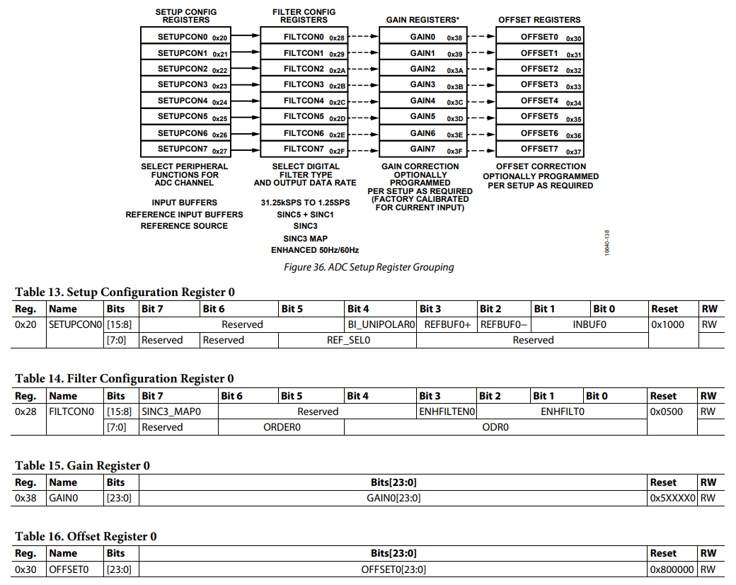
\CONFIGURATION OVERVIEW
After power-on or reset, the AD4111 default configuration is as follows:
• Channel configuration: Channel 0 is enabled, the VIN0 and VIN1 pair is selected as the input. Setup 0 is selected.
• Setup configuration: the analog input buffers are disabled and the reference input buffers are also disabled. The REF± pins
are selected as the reference source. Note that for this setup, the default channel does not operate correctly
because the input buffers need to be enabled for a VIN input.
• Filter configuration: the sinc5 + sinc1 filter is selected and the maximum output data rate of 31.25 kSPS is selected.
• ADC mode: continuous conversion mode and the internal oscillator are enabled. The internal reference is disabled.
• Interface mode: CRC and the data and status output are disabled.
• GPIO configuration: open wire detection is disabled.
Note that only a few of the register setting options are shown. This list is only an example. For full register information, see
the Register Details section. Figure 35 shows an overview of the suggested flow for changing the ADC configuration, divided into the following three blocks:
• Channel configuration (see Box A in Figure 35)
• Setup configuration (see Box B in Figure 35)
• ADC mode and interface mode configuration (see Box C in Figure 35)


SPI의 MISO핀이 RDY라서 어떻게 읽나 했는데 상태 레지스터에서 RDY를 보면 된다.


CONTINUOUS CONVERSION MODE
Continuous conversion mode is the default power-up mode.
The AD4111 converts continuously, and the RDY bit in the
status register goes low each time a conversion is complete. If CS
is low, the RDY output also goes low when a conversion is
complete


SINGLE CONVERSION MODE
In single conversion mode, the AD4111 performs a single
conversion and is placed in standby mode after the conversion
is complete. The RDY output goes low to indicate the completion
of a conversion. When the data-word has been read from the
data register, the RDY output goes high. The data register can
be read several times, if required, even when the RDY output goes
high.
If several channels are enabled, the ADC automatically sequences
through the enabled channels and performs a conversion on
each channel. When the first conversion is started, the RDY
output goes high and remains high until a valid conversion is
available and CS is low. When the conversion is available, the
RDY output goes low. The ADC then selects the next channel and
begins a conversion. The user can read the present conversion
while the next conversion is being performed. When the next
conversion is complete, the data register is updated; therefore,
the user has a limited period in which to read the conversion.
When the ADC has performed a single conversion on each of
the selected channels, it returns to standby mode.
If the DATA_STAT bit in the interface mode register is set to 1, the
contents of the status register, along with the conversion, are
output each time the data register is read. The four LSBs of the
status register indicate the channel to which the conversion
corresponds.


[링크 : https://www.analog.com/media/en/technical-documentation/data-sheets/ad4111.pdf]

'회사일 > 전자부품' 카테고리의 다른 글

ptn5110 usb-pd rdo 응답  (0) 2025.01.15
ad5292 wiper 값  (0) 2025.01.06
ads8598  (0) 2024.11.13
ad5292 write protect  (0) 2024.11.07
ad5291 shutdown mode  (0) 2024.09.26
Posted by 구차니
회사일/전자부품2024. 11. 7. 18:59

값을 써도 안바뀌는 것 같아 찾아보니

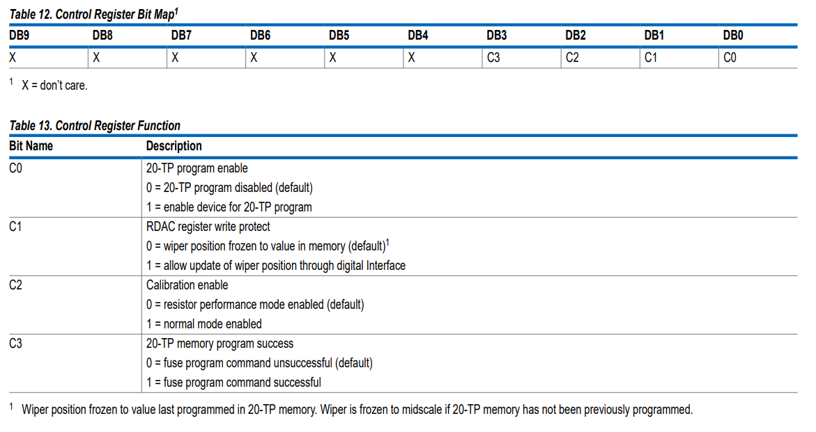
쓰기금지가 기본이고, 테스트 해보니 매번 쓰기금지를 풀어주고 값을 써야 되는 것 같은데 확인이 필요하다.

WRITE PROTECTION
On power-up, the shift register write commands for both the RDAC register and the 20-TP memory register are disabled. The RDAC write protect bit, C1 of the control register (see Table 12 and Table 13), is set to 0 by default.


[링크 : https://www.analog.com/media/en/technical-documentation/data-sheets/ad5291_5292.pdf]

'회사일 > 전자부품' 카테고리의 다른 글

ptn5110 usb-pd rdo 응답  (0) 2025.01.15
ad5292 wiper 값  (0) 2025.01.06
ads8598  (0) 2024.11.13
ad4111  (0) 2024.11.07
ad5291 shutdown mode  (0) 2024.09.26
Posted by 구차니
회사일/전자부품2024. 9. 26. 11:56

레오스탯 에서 Wiper Terminal을

A~B 사이의 가변 저항으로 사용하거나, W를 float 상태로 유지할 수 있다는데


해당 기능은 software shutdown 이라는 이름으로 제공된다.

근데 내용상으로는 첫 이미지가 아니라 세번째 이미지 처럼 W가 B와 붙고 A는 열리는것 같은데 다른걸 찾아야 하나?

THEORY OF OPERATION

SHUTDOWN MODE

The AD5291/AD5292 can be placed in shutdown mode by executing the software shutdown command, Command 8 (see Table 11), and setting the LSB, D0, to 1. This feature places the RDAC in a special state in which Terminal A is open-circuited, and Wiper W is connected to Terminal B. The contents of the RDAC register are unchanged by entering shutdown mode. However, all commands listed in Table 11 are supported while in shutdown mode. Execute Command 8 (see Table 11), and set the LSB, D0, to 0 to exit shutdown mode.

[링크 : https://www.analog.com/media/en/technical-documentation/data-sheets/ad5291_5292.pdf]

'회사일 > 전자부품' 카테고리의 다른 글

ptn5110 usb-pd rdo 응답  (0) 2025.01.15
ad5292 wiper 값  (0) 2025.01.06
ads8598  (0) 2024.11.13
ad4111  (0) 2024.11.07
ad5292 write protect  (0) 2024.11.07
Posted by 구차니