embeded/Cortex-M3 STM
HAL_FLASH_Program
구차니
2025. 7. 21. 16:40
특이한 건 블럭단위가 아니라는 것과 program은 있어도 Erase나 Read 함수가 안보인다는 점.
| // stm32f1xx_hal_flash.h HAL_StatusTypeDef HAL_FLASH_Program(uint32_t TypeProgram, uint32_t Address, uint64_t Data); HAL_StatusTypeDef HAL_FLASH_Program_IT(uint32_t TypeProgram, uint32_t Address, uint64_t Data); HAL_StatusTypeDef HAL_FLASH_Unlock(void); HAL_StatusTypeDef HAL_FLASH_Lock(void); HAL_StatusTypeDef HAL_FLASH_OB_Unlock(void); HAL_StatusTypeDef HAL_FLASH_OB_Lock(void); // stm32f1xx_hal_flash_ex.h HAL_StatusTypeDef HAL_FLASHEx_Erase(FLASH_EraseInitTypeDef *pEraseInit, uint32_t *PageError); HAL_StatusTypeDef HAL_FLASHEx_Erase_IT(FLASH_EraseInitTypeDef *pEraseInit); HAL_StatusTypeDef HAL_FLASHEx_OBErase(void); HAL_StatusTypeDef HAL_FLASHEx_OBProgram(FLASH_OBProgramInitTypeDef *pOBInit); void HAL_FLASHEx_OBGetConfig(FLASH_OBProgramInitTypeDef *pOBInit); uint32_t HAL_FLASHEx_OBGetUserData(uint32_t DATAAdress); |
[링크 : https://blog.naver.com/eziya76/220988141146]
[링크 : https://selpman.tistory.com/287]
음.. 플래시 영역은 0x0800 0000 으로 지정되어 있으니 거기서 부터 512KB (= 0x0008 0000)
인 0x0807 FFFF 까지 읽어보면 되려나

STM32F103RET 니까 아래 조건이려나
| /* High Density */ #if (defined(STM32F100xE) || defined(STM32F101xE) || defined(STM32F103xE)) #define IS_FLASH_PROGRAM_ADDRESS(ADDRESS) (((ADDRESS) >= FLASH_BASE) && (((*((uint16_t *)FLASH_SIZE_DATA_REGISTER)) == 0x200U) ? \ ((ADDRESS) <= FLASH_BANK1_END) : (((*((uint16_t *)FLASH_SIZE_DATA_REGISTER)) == 0x180U) ? \ ((ADDRESS) <= 0x0805FFFFU) : ((ADDRESS) <= 0x0803FFFFU)))) #endif /* STM32F100xE || STM32F101xE || STM32F103xE */ |
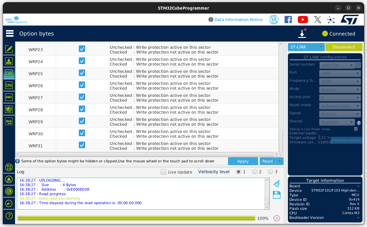
그런데 STM32CubeProgrammer로 확인해보니
512KB 맞고 sector는 0에서 255까지 256개 * 2KB

Write Protect는 0에서 31 까지 총 32개.. 8개 섹터당 1개의 write protect 인가


| 2.4.2 Write protection In high-density and connectivity line devices, from page 0 to page 61, write protection is implemented with a granularity of two pages at a time. The remaining memory block (from page 62 to page 255 in high-density devices, and from page 62 to page 127 in connectivity line devices) is write-protected at once. |
0~61 까지는 2개씩 해서 총 31개 write protect로 상세하게 제어되고
62~255까지 퉁쳐서 1개,
합계 32개의 write protect로 제어된다.
| Depending on the selected boot mode, main Flash memory, system memory or SRAM is accessible as follows: Boot from main Flash memory: the main Flash memory is aliased in the boot memory space (0x0000 0000), but still accessible from its original memory space (0x800 0000). In other words, the Flash memory contents can be accessed starting from address 0x0000 0000 or 0x800 0000. Boot from system memory: the system memory is aliased in the boot memory space (0x0000 0000), but still accessible from its original memory space (0x1FFF B000 in connectivity line devices, 0x1FFF F000 in other devices). Boot from the embedded SRAM: SRAM is accessible only at address 0x2000 0000. Embedded boot loader The embedded boot loader is located in the System memory, programmed by ST during production. It is used to reprogram the Flash memory with one of the available serial interfaces: In low-, medium- and high-density devices the bootoader is activated through the USART1 interface. In XL-density devices the boot loader is activated through the following interfaces: USART1 or USART2 (remapped). In connectivity line devices the boot loader can be activated through one of the following interfaces: USART1, USART2 (remapped), CAN2 (remapped) or USB OTG FS in Device mode (DFU: device firmware upgrade). |